Showing posts with label Python Photogrammetry Toolbox. Show all posts

Tuesday, 16 June 2015

OpenMVG VS PPT

Hi all,
as I promised, we are back with new post in ATOR. We start today with an experiment we wanted to do since long: a comparison between two Structure from Motion - Muti View Stereoreconstruction (SfM - MVS) suite. The first is Python Photogrammetry Toolbox, developed by +Pierre Moulon some years ago and integrated in ArcheOS 4 (Caesar) with the new GUI (PPT-GUI) written in Python by +Alessandro Bezzi and me. The second one is the evolution of PPT: openMVG, which Pierre is developing since some years and that will be integrated in the next releases of ArcheOS.
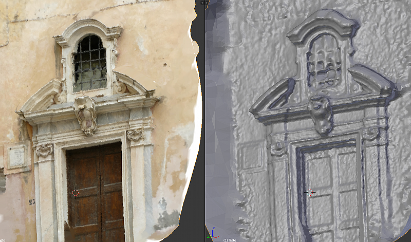
Our small test regarded just four pictures taken with a Nikon D5000 on an old excavation. We want to point out the speed of the overall process in OpenMVG, which gave a result compatible with the one of PPT.
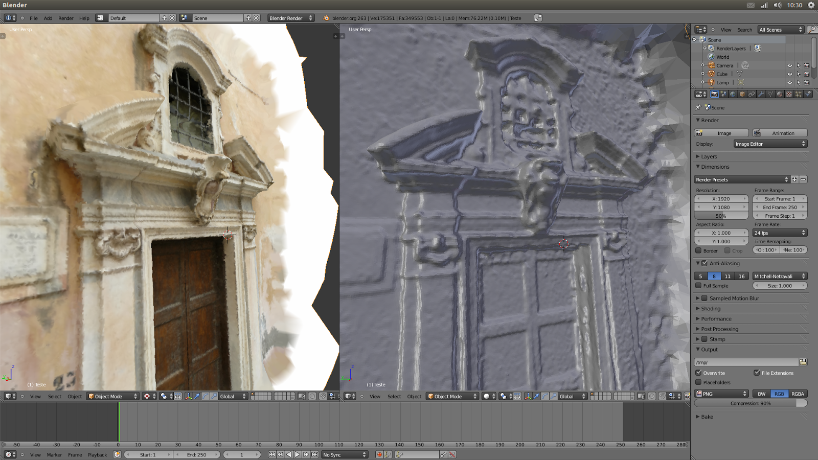
In the image below you can have an overview (in +MeshLab) of the two pointclouds generated bye the different software: openMVG processed a ply file with 391197 points, while PPT gave us a result with 425296 points.


Comparison of the two models generated by opnMVG and PPT

The main different stays in the processing time. In fact, while PPT needed 16 minutes, 11 seconds and 25 tenths, openMVG complete the model in just 3 minutes, 28 seconds and 20 tenths.
Here below I report the log file of openMVG, where you can see each step of the process:

STEP 1: Process Intrisic analysis - openMVG_main_CreateList took: 00:00:00:00.464
STEP 2: Process compute matches - openMVG_main_computeMatches took: 00:00:01:13.73764
STEP 3: Process Incremental Reconstruction -  openMVG_main_IncrementalSfM took: 00:00:00:47.47717
STEP 4: Process Export to CMVS-PMVS - openMVG_main_openMVG2PMVS took: 00:00:00:00.352
STEP 5: Process CMVS-PMVS took: 00:00:01:25.85958
--------------------
The whole detection and 3D reconsruction process took: 00:00:03:28.208258

We will go on in working and testing openMVG, hopfully posting soon news about this nice software.

Have a nice day!

Acknowledgment

Many thanks to +Pierre Moulon and +Cícero Moraes for the help!

Thursday, 18 April 2013

Scanning skulls to forensics with PPT GUI and Meshlab, the evolution of methodology


Following with the develop of a protocol to formalize the use of PPT GUI on forensics science, we are simplifying and making more accurate the obtaining of 3D skull using photos.


Instead to use Blender to joint the parts of the skull, the entire work is made in Meshlab.

If the artist wanna use the skull to do a reconstruction, he/she can import it on Blender with tranquility.

The advantage of this methodology is that you can reconstruct the entire skull using the best part of two or more sequence of photos.


The work is being developed by Cícero Moraes (me), Dr. Paulo Miamoto and other researchers from Brazil and Czech Republic.

Acknowledgments to Prof. Petra Urbanová, head of the Laboratory of Morphology and Forensic Anthropology - Faculty of Sciences, Masaryk University, Brno, Czech Republic; Prof. Rodolfo F. H. Melani, head of the Forensic Anthropology and Dentistry Laboratory (OFLAB/FOUSP) - Faculty of Dentistry, University of São Paulo, São Paulo, Brazil; Mikoláš Jurda - Laboratory of Morphology and Forensic Anthropology - Faculty of Sciences, Masaryk University, Brno, Czech Republic.

In order to reveal the limitations of the PPT GUI, a test of scanning was made in bad conditions for this type of acquiring data.


A skull (with reflecting-light) was photographed in a room of low lights an a simple camera, without isolate the scenario.

Fortunately the result was good, at least to make a forensic facial reconstruction.

The test was made thanks to the help of Prof. Dr. Joel A. Sousa and Lis Caroline.

Sunday, 7 April 2013

PPT GUI and Blender, an interesting solution to forensics

Since I started to study forensic facial reconstruction, more or less one year ago, I had the opportunity to know a lot of interesting things and people that works in a couple of different fields, but with something related to forensics.

Currently me and Dr. Paulo Miamoto scan a skull using SfM to test the accuracy of the PPT GUI in relation to laser scanning.

This is very important because shows an interest of instituitions  related to forensics science relative to free software.

If is proved that the accuracy of SfM is compatible with the laser scan, it can be an important and revolutionary opportunity to take the accessible technology for a lot of parts of the world that never thought about use it before.

We hope this attempt be well succeded.

Acknowledgements to Mikolaš Jurda and Prof. Petra Urbanová, head of the Laboratory of Morphology and Forensic Anthropology of the Faculty of Sciences, Masaryk University (MUNI); Prof. Rodolfo Francisco Haltenhoff Melani, head of the Laboratory of Forensic Anthropology and Dentistry of the Faculty of Dentistry, University of São Paulo (OFLAB-FOUSP); and CAPES Foundation, Brasília - Brazil.

Wednesday, 20 March 2013

Converting a video into a 3D mesh and reconstructing a face


The technology of SfM allow you convert, with great precision and quality, some photos into a 3D mesh.

The problem is when you don't have the photos and need to find other ways to reconstruct an object.

Fortunatelly, the Python Photogrammetry Toolbox (SfM) works well in a couple of possibilities, and like you saw in the video above, also with this type of media.


The video downloaded, shows the Budapest Múmia Projekt of the Szépművészeti Múzeum.

This project was a multidisciplinary effort not only to reconstruct the face of the mummies, but the panorama of their past lifes too.

To put the object in the scale, I use other video that show the CT-Scan with a scale at side.

Even working with a low quality reconstructed mesh, the result of the reconstruction was relatively compatible with the oficial bust made by Dr. Kustár Ágnes.

If you wanna see the step-by-step of the process, I created an album and shared it here: https://plus.google.com/photos/115430171389306289690/albums/5856903432134303473

I hope you enjoy.

A big hug and I see you in the next!


Saturday, 16 March 2013

The Faces of Evolution - Exhibition of hominids forensic facial reconstructions


May 18th through July 31st, 2013 will happen in the big and beautiful Curitiba city in Brazil, the exhibition The Faces of Evolution.

Near the replicas of skull of hominids will have nine panels with forensic facial reconstructions.

The exhibition will happen now, but the history started here in ATOR some months ago.

The methodology developed to model the majority of the faces was used for the very first time in Alberto di Trento's reconstruction.


On that occasion the Arc-Team presented a paper at the event Giovani Antropology (Italy), where they described the methodology for forensic facial reconstruction using only free software.


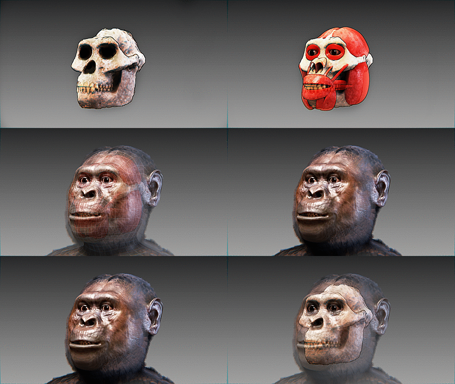
Following the events, we initiated Project Taung. If before we had rebuilt a modern human this time we would rebuild a hominid remote, then the Taung Child.

Beyond the Arc-Team Group, has joined the project Prof. Dr. Nicola Carrara University of Padua.


We were able to reconstruct the face of the Taung child fastly, thanks to a methodology developed previously.

We had a largely positive feedback, both personalities linked to forensic facial reconstruction, as those related to 3D modeling, as the creator of  Blender, Mr. Ton Roosendaal.


Several media outlets broadcasted stories (see the comments) on the reconstruction of the Taung child, as the Jornal de Brasilia above.

After the successful reconstruction of hominid remote, we got in touch with the archaeologist Prof. Dr. Moacir Elias Santos of the Archaeological Museum of Ponta Grossa and Prof. Esp. Vivian Tedardi of Rosicrucian and Egyptian Museum in Brazil and we began a series of modeling which culminated in the exhibition the Faces of Evolution, described here.


The Cro-Magnon man.

The Turkana Boy.

The Homo heildelbergensis.

The Homo neanderthalensis.

The Homo habilis.


And last but not least, the Homo floresiensis.


This was a brief description of the exhibition and its history. Now, we expect the event date arrives, while others look for fossils to be rebuilt.

A big hug!

Monday, 11 March 2013

CloudCompare: how to georeference a point cloud using data from total station (local coo system)

Hi all,
I made a new videotutorial about rectification using CloudCompare v. 2.4. In this video i use data from total station (local coordinates system) to rectify a point cloud. The point cloud is realized using Python Photogrammetry Toolbox.


Saturday, 9 March 2013

SfM for Underground Documentation

Since last October Arc-Team is working on a challenging project about World War 1 on the southwestern frontline 1915-18.
Austro-Hungarian artillery piece in wintry position 1916
In a few years we will celebrate the 100st recurrence of the Italian declaration of war against the Austro-Hungarian Empire in May 1915.
For that reason the South-Tyrolean Heritage Departement was starting an extensive archaelogical survey campaign in high alpine environment up to 3900 m.s.l.
We've had to find out a rapid, lightweight and low cost method to document the uncountable amount of structures along both front lines.
The area of our pilot project is an approximately 6 sqkm large high plane between 2000 and 2300 m.s.l. called Plätzwiese. Between 1915 and 1917 it was a strongly fortified second line artillery position of the Austro-Hungarian Army.
Crew Cavern
Because of the seclusion of this area, today there we can find some of the best preserved residues of WW1 in Europe. We expect a total amount of more than 1000 archaeological remains just in this sector.
One of the major challenges is the documentation of the numerous tunnels and caverns driven in to the rock to protect troops and material from enemy artillery fire.

View towards the exit


We apply SfM to obtain pointclouds of the interiors, dealing with difficult conditions of illumination and space. After placing GCP's around the entrance(s) and measuring them with our DGPS, we start with one or more sequences of pictures in the entrance area, advancing along the tunnels, turning at their end and coming back to the starting point.

In the dark we use of course a tripod to allow long exposures and some torches, to illuminate shadow areas.
In this way we've taken up to 300 pictures for one single structure.
Various attempts of processing them in Python Photogrammetry Toolbox divided in a few single sequences, gave us some indication of the most advantageous way of photographing.

Point Cloud in MeshLab v1.3.2.

For good results we need to follow two important rules:

  1. Redundancy: The same point has to be visible in much pictures possible.
  2. Long baseline: To obtain correct geometrical information, the projection centers of the sensors have not to be to close together.

  • Taking a just a single photo-sequence along one way of the cavern, causes often problems with redundancy and subsequently lead to empty areas in the pointcloud, especially along the ceiling of the cavern.
    Recording strategy 01
    • Another of the experiences gained, is that the software has big difficulties to match features form the photo-sequence taken on the way inwards, with features from the photo-sequence taken on the way back to the entrance of the tunnel.
    Recording strategy 02

    • We get the best results advancing on two parallel lines, as well on the way in, as on the way out of the structure.
    Final result 01

    Finally we processed the parallel sequences of each direction and referenced them after in Cloudcompare in the way how Ale Bezzi described it.
    Final result 02
      In June 2013, after the thaw, we will resume fieldwork in Plätzwiese and we hope to  acquire further experience.


      Friday, 28 December 2012

      How to make 3d scan with pictures and the PPT GUI


      More than ever before 3D models have become a "physical" part of our life, how we can see in the internet with 3D services of printing.

      Some people have many difficult to get a model to print... well, not only to print, but to write an scientific article, make a job, or just have fun.

      With this tutorial you'll learn how to scan 3D objects to use it the way you want.

      Before all, I would like to thank all friends that help me to write this tutorial mainly Bob Max of the ExporttoCanoma's blog that publish interesting posts about GIS and now are interested in SfM (like all good nerd who works with 3D).

      It's impossible to forget Pierre Moulon, the developer os Python Photogrammetry Toolbox (PPT), and Luca Bezzi e Alessandro Bezzi, developers of the ArcheOS and PPT GUI.

      This tutorial includes many examples and some source files that will help you to learn how works the PPT.

      So, lets go!


      The image above show the object that we'll scan in this tutorial


      How to make 3d scan with pictures and PPT GUI

      First of all is necessary to download the Python Photogrammetry Toolkit on: http://www.arc-team.homelinux.com/arcteam/ppt.php


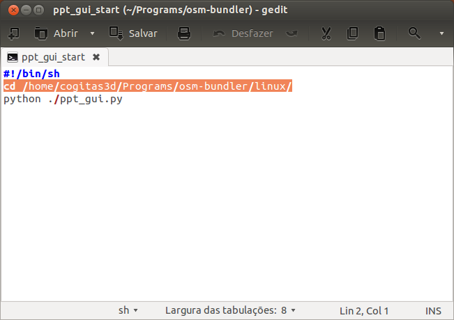
      After download and unzip you have to edit the ppt_gui_start file putting the right path of the program (in orange).


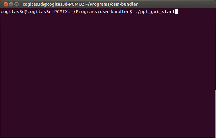
      Now, if you are in Linux is only run the script edited:
      $ ./ppt_gui_start
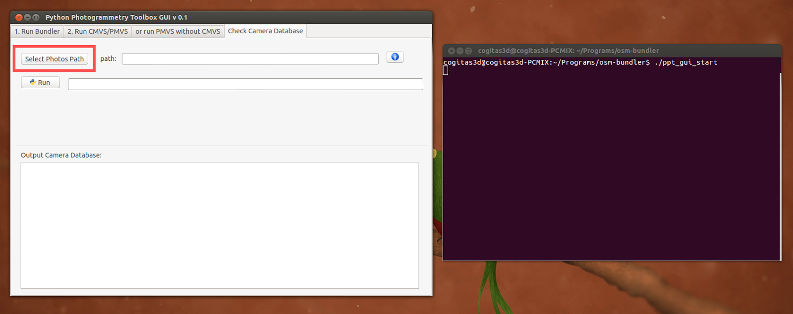
      Once the program is opened, click on “Check Camera Database”.

      With the Terminal/Prompt by side, click in “Select Photos Path”.

      Choose the path and then click on “Open”.

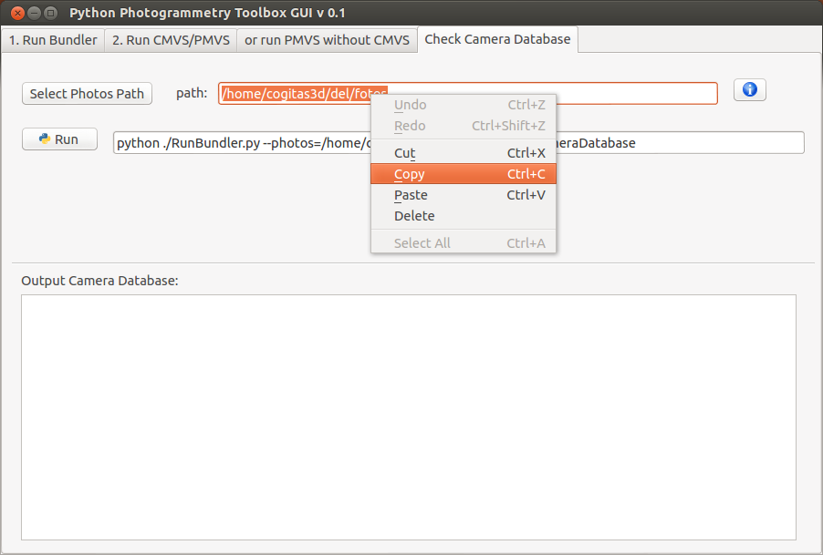
      Click in “Run” and wait a little.


      If all is OK, you’ll see a message in the Terminal:

      Camera is already inserted into the database
      If not, you can customise with this videotutorial:

      Now, make a copy of the path.


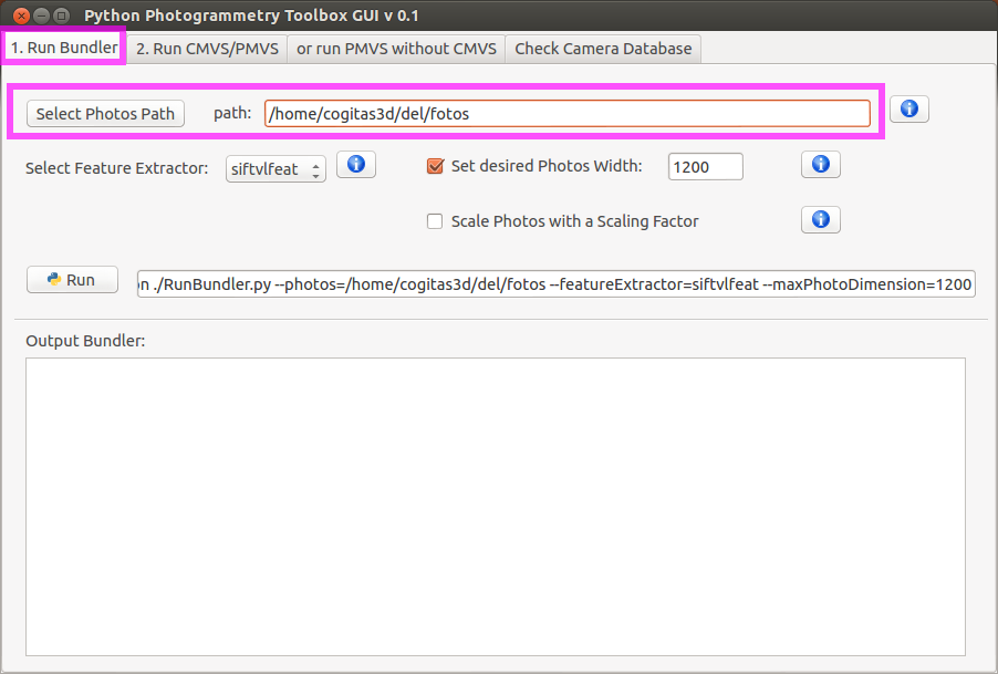
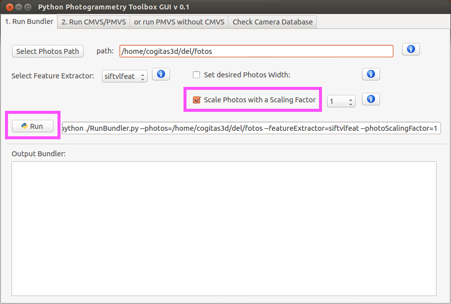
      1) Go to “Run Bundler”.
      2) Past at “Select Photos Path”.

      1) To make a good scan quality, click on “Scale Photos with a Scaling Factor”, by default, the value will be 1. If you have a computer with less power of processing, do not make this step (1), and go directly for the step bellow (2).

      2) Click on “Run”.

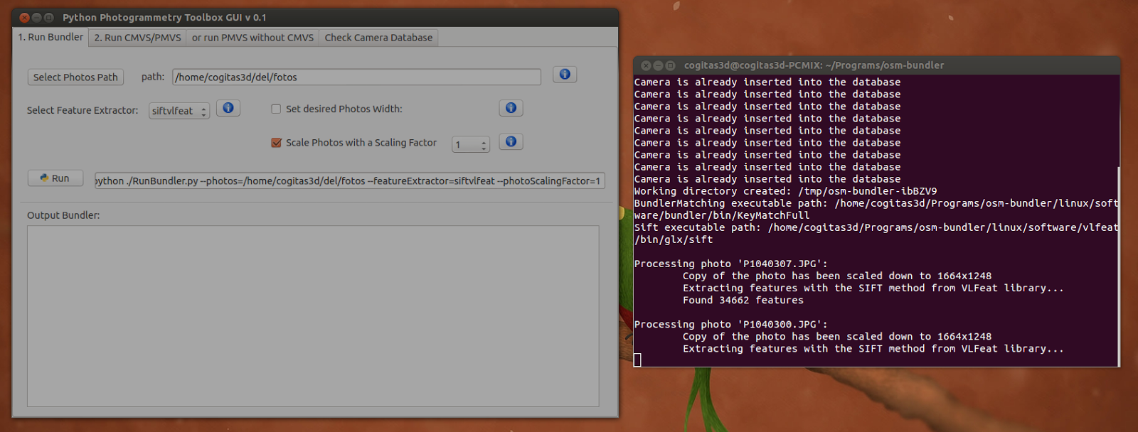
      Wait a few minutes, the program will solve the point clouds.


      You will know that the solve is done when in the Terminal appear the message:

      Finished! See the results in the '/tmp/DIRECTORY' directory

      In this case the message was:
      Finished! See the results in the '/tmp/osm-bundler-ibBZV9' directory

      The Nautilus will be opened to, showing the directory with the files.


      OBS.: If you area really curious, you can open the Bundle directory and see the .PLY files in Meshlab. But is better wait, because this point clouds is not good to make reconstruction/convertion into a mesh.


      Go to the Terminal, where appeared the path with the solve, and make a copy of it.


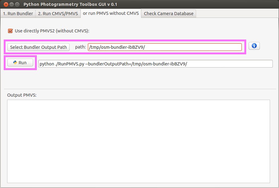
      1) Go to the “or run PMVS without CMVS”
      2) Click in “Use directly PMVS2 (without CMVS)”


      1) Paste the path in “Select Bundler Output Path”
      2) Click on “Run


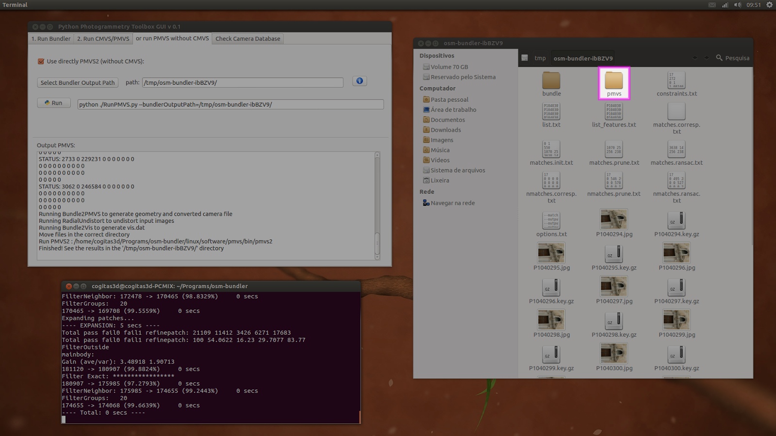
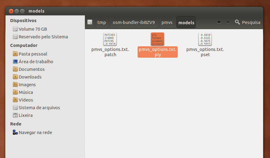
      When the process is done, you’ll see a new directory named “pmvs” appear.


      So, you have to enter in “models” and search for a file named “pmvs_options.txt.ply”. If all is OK it is the final process of solving.


      OBS.: It’s a good idea copy the osm-* directory for your home, because it will be lost in the next boot, because the /tmp directory.

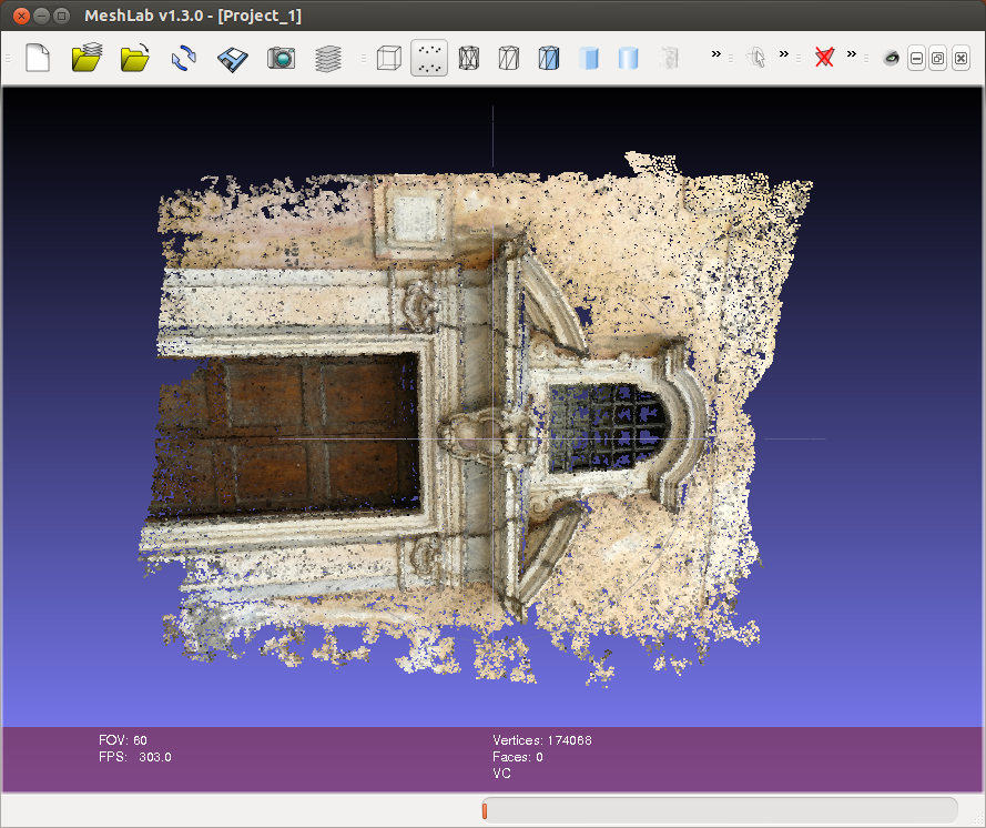
      When you open the “pmvs_options.txt.ply” file in Meshlab you’ll see that the points cloud is really dense now, with almost the quality of a picture.


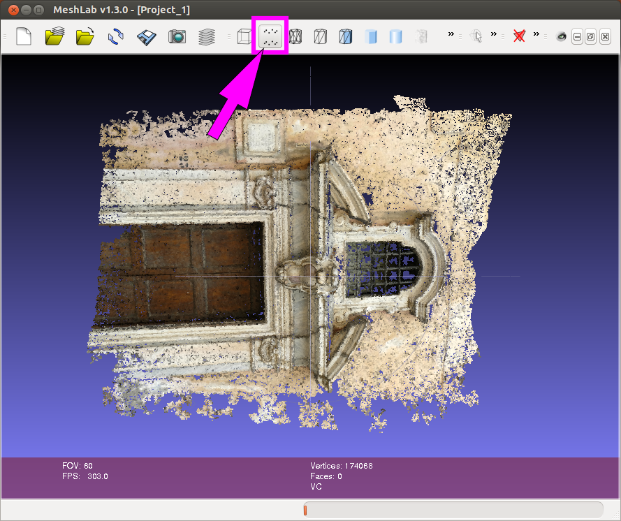
      Only appear a picture or a mesh... notice that the “Points” is a way of view selected.


      If you select “Flat Lines” for an exemple, the points clouds will desappear... because, obviously... it’s a --points-- cloud.


      Click again in “Points” to see the points cloud and:


      1) Click on “Show Layer Dialog” (A)
      2) So, will appear a new element in the interface with the name of the object, in this case “pmvs_options.txt.ply” (B)


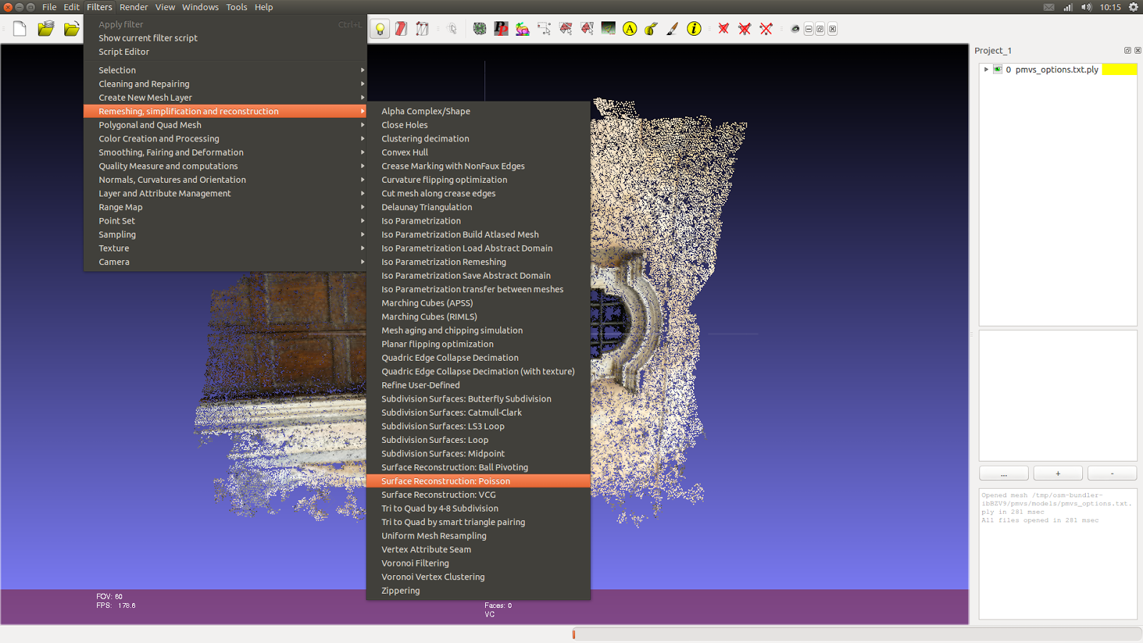
      Go to “Filters” -> “Remeshing, simplification and reconstruction” -> “Surface Reconstruction: Poisson”


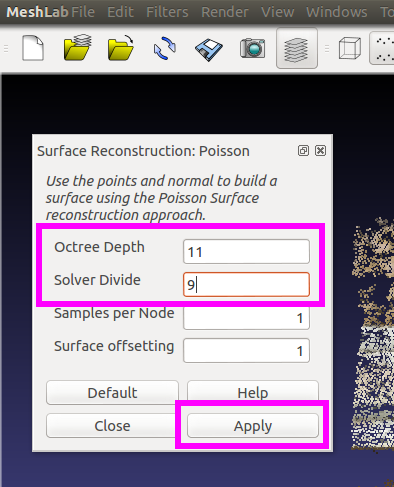
      A new window will appear with the defaults value of “Octree Depth” and “Solver Divide”

      1) Change the values to:
      Octree Depth: 11
      Solver Divide: 9


      2) Click in “Apply”


      OBS: This vlues can crash the program if you computer do not have a good power of processing.


      If all runs OK, you will notice two things:


      1) A lot of new write points over the reconstruction.
      2) A new layer in the upper right named  “1 Poisson mesh *”


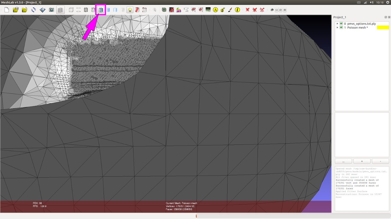
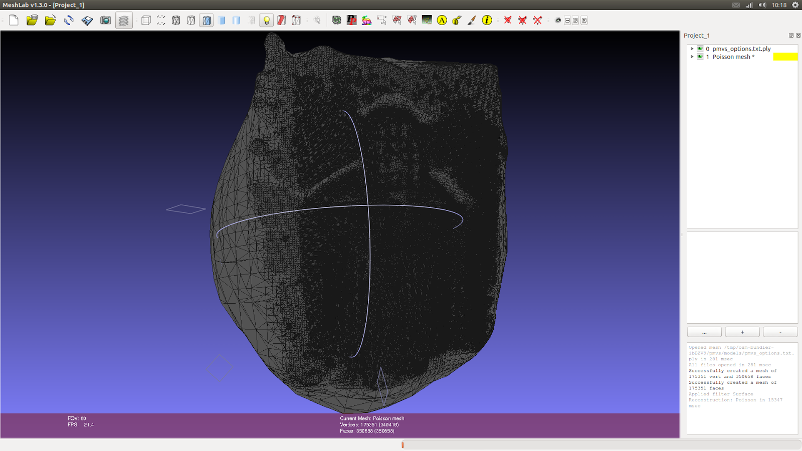
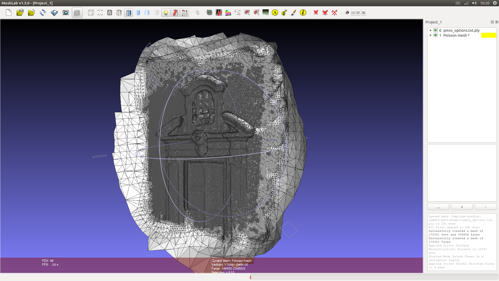
      But, when we comeback to “Flat Line” to see the mesh, strange things can happen. In this case, the algotithm Poison created one type of ball to reconstruct the mesh.


      We can see it better when we orbit away the model.


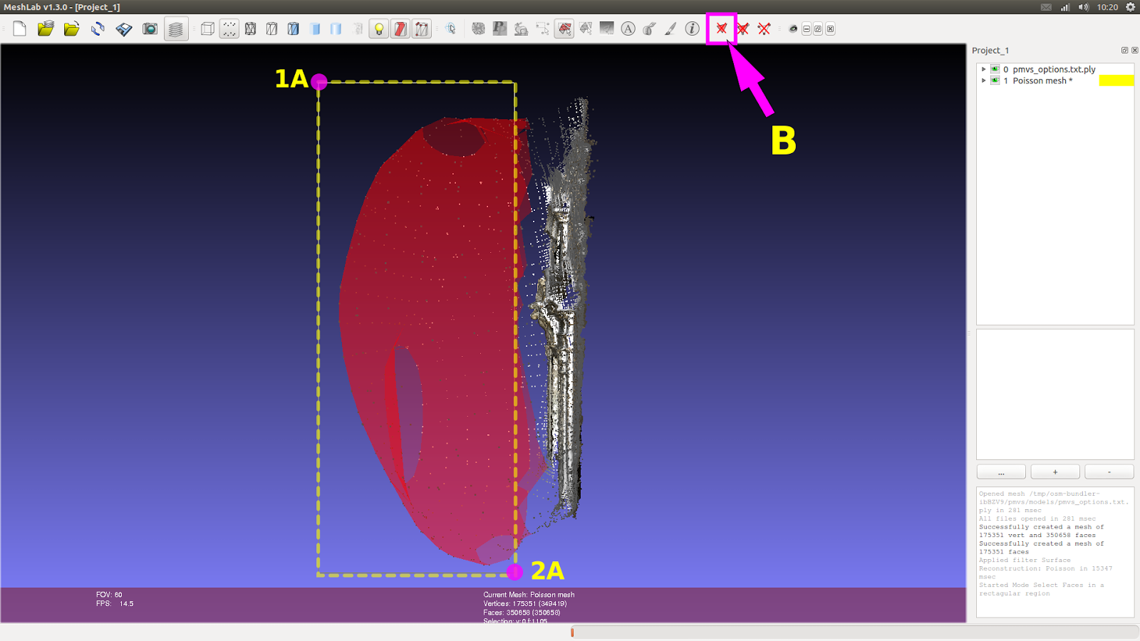
      So, to make the door visible, we:


      1) Come back to the “Points” view (A)
      2) Orbit the scene to see the side of the door.
      3) Click on “Select faces in a rectangular region”


      So:


      1) We make a window selection on the region that will be deleted (1A-2A)
      2) Click on “Delete the current set of selected faces”.


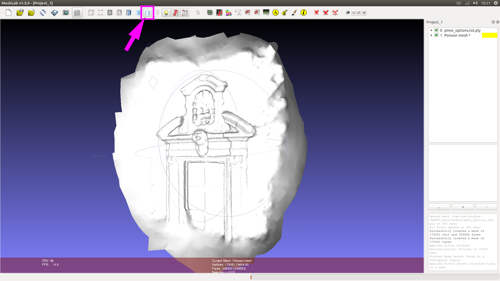
      Now we can see the mesh in the correct side.


      But, when we change the type of view to “Smooth”, we see the mesh write without the colors of the points cloud.


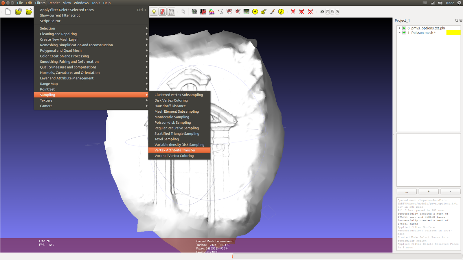
      To paint the mesh with the color of the points cloud we can go to:
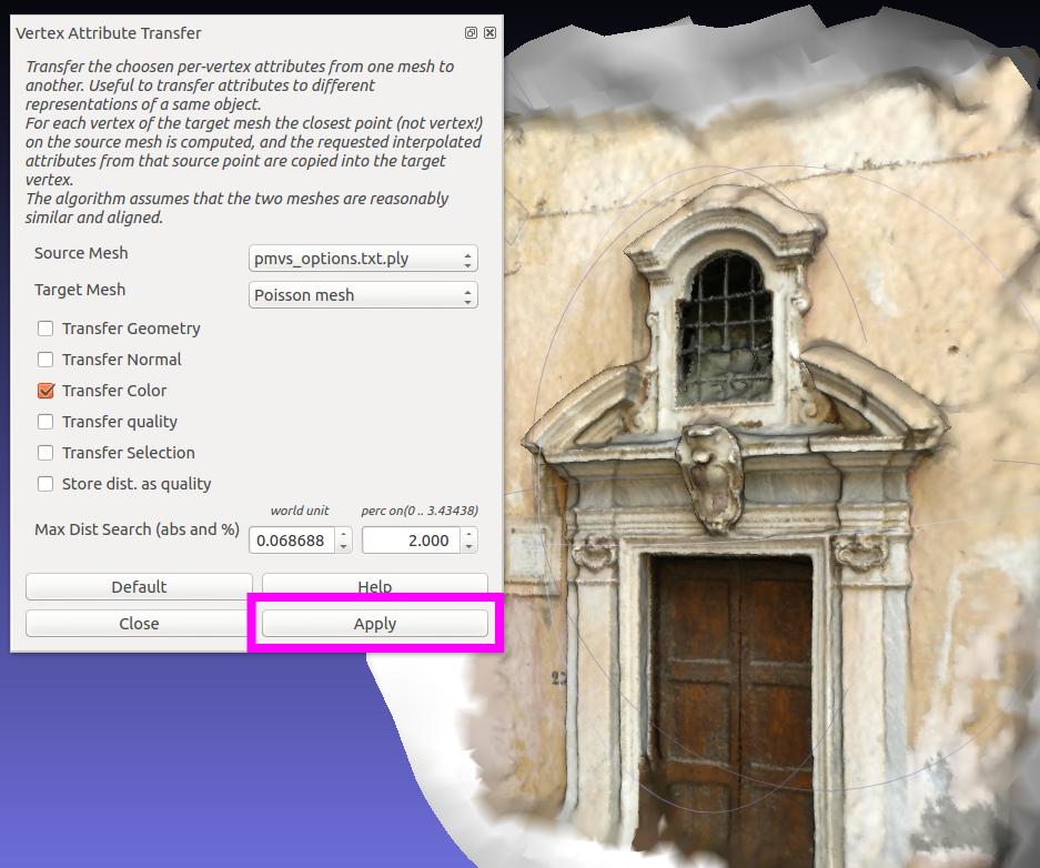
      Filters -> Sampling -> Vertex Attribute Transfer


      A substancial part of this step was learned with this video: http://vimeo.com/14783202


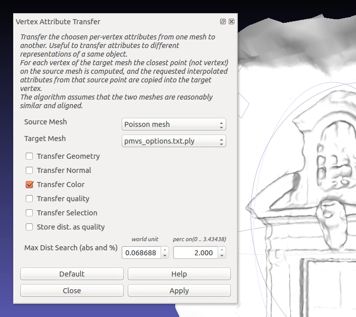
      A new window will appear.


      You’ll have to invert the objects, because the “pmvs_options.txt.ply” is the real source mesh, that will be the base to paint, and the “Poisson mesh” will receibe the colors, so it is the Target mesh.


      When you click on “Apply” immediatly you’ll see the mesh colored, like the image above.


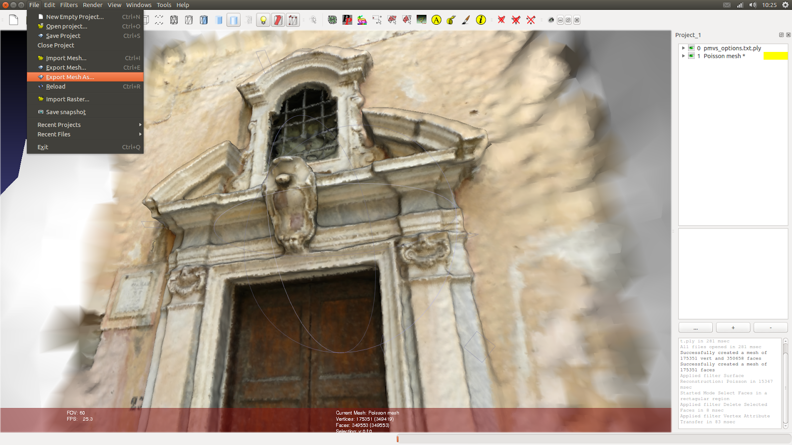
      If you wanna send this mesh to other software like Blender, you can go to:


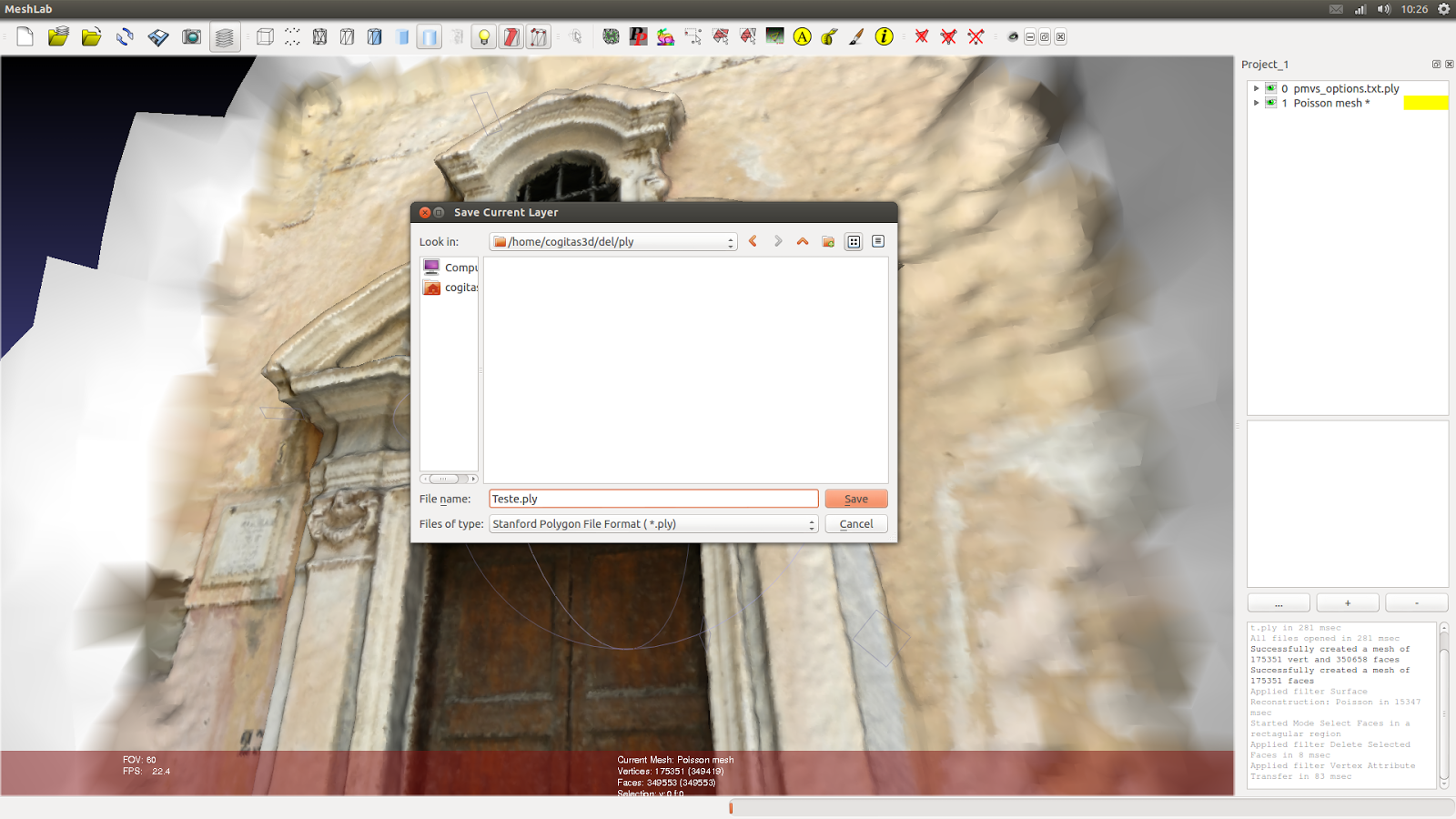
      File -> Export Mesh As..


      Choose a place to save the .PLY file.


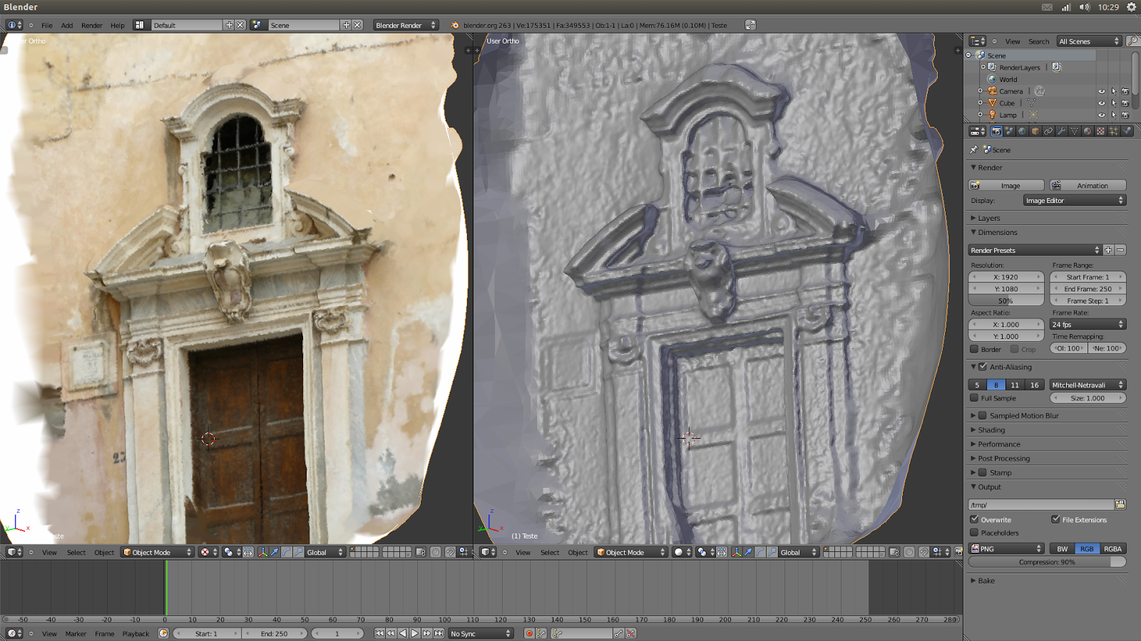
      If all is OK, the mesh will be imported on Blender (or other software) perfectly.


      Other examples:


      If you wanna you can download a sequence of pictures of Taung Child (anim. above) to make your own test here: 

      And see if match with the final result here:


      I hope it has useful to you.


      A big hug and I see you in the next article!


      BlogItalia - La directory italiana dei blog Creative Commons License
      This work is licensed under a Creative Commons Attribution 4.0 International License.