Friday 28 June 2013

A skeleton of Medicine's History Museum have his face revealed

Some days ago I was looking for some skull to reconstruct and present in my talk on Blender in Brazil. The talk will happen in the FISL14, one of the greatest free software conference in the world.

Fortunately I received an email from the Medicine's History Museum of Rio Grande do Sul (MUHM), that needed a forensic facial reconstrucion.

The nickname of the skeleton is Joaquim. He was a prisoner that died like a indigent in France in 1920. In 2006 he was donated to the museum by a family of doctors.

I ordered a CT-Scan and the people of the museum sent me not only the head, but all Joaquim's body.

So, I'll reconstruct all the body, but for now only the head was done.

To reconstruct the bones in 3D I used InVesalius, a CT-Scan reader open source. It was necessary export some files with different configurations, because the amount of data is huge.

Like I said, in this first part of Joaquim Project I'll reconstruct only the face. In the Meshlab I cleaned the noise of 3D reconstruction of CT-Scan.

The skull was not complete. To get the mandible I made a projection using Sassouni/Krogman method shown in Karen T. Taylor's book.

With the help of forensic dentist Dr. Paulo Miamoto, we get the range of Joaquim's age: 30-50.

The tissue depth markers was put.

So it was possible to sketch the profile of the face.


 The muscles was glued at the skull.


 Finally, the skin, the cloth and the hair was put.

I don't know if Joaquim really was born in France, but he appear a French man.

Thanks to:
Éverton Quevedo and Letícia Castro from MUHM.

A big hug and I see you in the next!

Thursday 27 June 2013

The Taung Child is now touchable, thanks to 3d printing

As Luca Bezzi said in his presentation in Catania, the next step in the Taung project was 3d printing; in a previous post, I explained some issues we found in the original mesh. But thanks to Cicero's suggestions, the problems have been fixed, and 3 days ago Kentstrapper finally printed the Taung Child skull.

Here are some images:


The .stl model


Kentstrapper strongly believe that 3d printing can be a real revolution in education and culture. And, of course, in archaeology 3d printing should also be a great change in museum expositions: facial reconstructions, scale models of ancient buildings or (as in this case) plastic copies of finds could make archaeology much more easily understandable for visitors.

HERE you can download the final .stl file of the skull.


Tuesday 25 June 2013

The Taung Project, an open research

This post is to share the presentation I did in Catania (Sicily), during the ArcheoFOSS 2013. The topic is the Taung Project, analyzed from a free and open source point of view. This experience, in fact, has been a perfect pilot project of "open research", developed with open tools and sharing at the same time knowledge and data.
I will not dwell any further on the topic of the presentation in this post, being this subject described in the video below...


... I will just report some technical data. 
 First of all (in alphabetic order), the authors of the presentation, which are not mentioned in the video (sorry, I forgot it...): Alessandro Bezzi (Arc-Team), Luca Bezzi (Arc-Team), Nicola Carrara (Anthropological Museum of Padua University), Cicero Moraes (Arc-Team/Blender Brazil), Moreno Tiziani (Antrocom Onlus).
Secondary, the software I used for the slides, which is the object of most of the questions I have been asked after the presentation :). Well, this program is called impress.js and it is released under the MIT and GPL licenses. Here you can see an example of what you can do with this tool and here is the source code.
That's all for now. I hope that the discussion about the concept of "open research" will go on with new contributes... Stay tuned :).

Monday 24 June 2013

An example of “local reprojection” from WGS84 to Gauss-Boaga Rome40 with SQLite/SpatiaLite

A common problem for many Italian GIS users in archaeology is to reproject vector features from WGS84 to Gauss-Boaga Rome40 (national Spatial Reference System in Italy till 2012). For shapefiles this transformation can be performed by specific GIS tools, often based on PROJ library (http://trac.osgeo.org/proj/), by OGR utilities (i.e. ogr2ogr: http://www.gdal.org/ogr/) or others standalone software.
In SQLite/SpatiaLite the reprojection between 2 different Spatial Reference Systems (SRS) is provided by “Transform” function (for complete description and syntax see: http://www.gaia-gis.it/gaia-sins/spatialite-tutorial-2.3.1.html#t5): it’s possible to convert data in all the many Spatial Reference Systems stored in SpatiaLite’s “spatial_ref_sys” table and coded by SRID (Spatial Reference Identifier) and EPSG dataset. For example, to transform a vector from WGS84 to UTM ED50 it's enough to update geometry field in your table with the following SQL command:

UPDATE your_table SET geometry_field = Transform(geomWGS84, 23032);

where “geomWGS84” is a geometry field in WGS84 system (EPSG:4326) and “23032” is EPSG value for UTM ED50 zone 32 N.
The problem is that the reprojection between global systems often yields an approximate and imprecise result. For reaching a more accurate outcome a “local reprojection” is required: it is feasible using specific parameters of transformation (translation, rotation and scaling), different for each part of territory.
My example is about Veneto Region in Northern Italy. I needed to reproject some points, representing archaeological sites of this Region, from WGS84 to Gauss-Boaga Rome40 – West (EPSG:3003). I tested this transformation in SpatiaLite simply using the Spatial Reference Systems stored in spatial_ref_sys table; so I executed the SQL command

UPDATE my_table SET geometry_field = Transform(geom4326, 3003);

where “geom4326” is the geometry field recording the geometries of my points in WGS84 and “3003” is the EPSG value for Gauss-Boaga Rome40 W. The outcome was not good: the points converted were located till 80 meters far away from the correct position.
In order to reduce this displacement, I read this post of Flavio Rigolon about reprojection with ogr2ogr and I adapted that solution for SQLite/SpatiaLite (but I think it could work also with PostGIS in similar way).
In particular, I added a new Spatial Reference System (SRS) in spatial_ref_sys table:

INSERT INTO spatial_ref_sys VALUES(30033003,'epsg',30033003,'Veneto 3003','+proj=tmerc +ellps=intl +lat_0=0 +lon_0=9 +k=0.999600 +x_0=1500000 +y_0=0 +units=m +towgs84=-104.1,-49.1,-9.9,0.971,-2.917,0.714,-11.68','');

My new SRS is identified by SRID and EPSG value “30033003”, is called “Veneto 3003” and has the same geodetic attributes (projection, ellipsoid, units, etc.) of Gauss-Boaga Rome40, but with the addition of 7 trasformation parameters (translation + rotation + scaling) defined by attribute “towgs84”.
For testing precision of my new SRS I selected 5 points of Veneto Region identifiable in WGS84 maps and in Gauss-Boaga Rome40 maps (CTR = “Carta Tecnica Regionale” at scale 1:10.000). I transformed my points from WGS84 SRS (EPSG:4326) to Gauss-Boaga Rome40 SRS (EPSG:3003) and to my new SRS “Veneto 3003” (EPSG:30033003). In the following images you can estimate the different positions for points transformed respectively in global EPSG:3003 and in local EPSG:30033003.


These two simple plots visualize the displacement (in meters) between correct position and points transformed.
The min, max and mean value of x (longitude) error of transformation from EPSG:4326 to EPSG:3003 is: 18.57, 36.26, 23.23 meters;
the min, max and mean value of y (latitude) error of transformation from EPSG:4326 to EPSG:3003 is: 63.36, 71.95, 68.74 meters;
the min, max and mean value of x (longitude) error of transformation from EPSG:4326 to EPSG:30033003 is: 0.49, 15.14, 4.31 meters;
the min, max and mean value of y (latitude) error of transformation from EPSG:4326 to EPSG:30033003 is: 3.3, 11.6, 6.8 meters.

[Part of this error is due to my test data: the 5 points in WGS84 have been selected from Googleearth and not recorded with a GPS and the same points identified in CTR are affected by the resolution of paper maps (“errore di graficismo” in Italian). I hope to do a more accurate test in the coming months...].

A mean error between 4 and 7 meters is acceptable for my purposes and in general for many archaeological works: in fact this error is not far from the best accuracy of portable GPS device (often used in archaeological surveys) and certainly smaller than positioning inaccuracy of many archaeological sites found in 19th or in the first half of 20th century. More accurate parameters of transformation (the 7 roto-traslation and scaling parameters of towgs84) could reduce this error, in particular in the Western and Northern part of Region where the distance from correct position seems to be greater.

That's all. If you know other (and faster) methods or if you detect mistakes in my post, please let me know. Any suggestions are welcome.

Denis Francisci


P.S. To enlarge the first image, open it in a new tab or window!

Thursday 20 June 2013

Kinect - Infrared prospections

Despite what I wrote at the end of this post, it looks like that Kinect is not really the best option for archaeological underground documentation, or for any other situation in which it is necessary to work in darkness.
I already tested the hardware and the software (RGBDemo) at home, simulating the light conditions of an underground environment, and the result was that Kinect scanned in 3D some parts of an object (a small table), with great difficulties. 
My hope was that the infrared sensors of Kinect were enough to record the objects geometries also in darkness, as actually happened. The problem was that probably RGBDemo, to work properly, needs also RGB values (from the normal camera). Without colors information the final 3D model is obviously black (as you can see below), but (and this is the real difficulty) it seems that the software loses a fundamental parameter to keep tracking the object to document, so that the operations become too slow and, in most cases, it is not possible to complete the recording of a whole scene. In other words the documentation process often stops, so that after it is necessary to start again or simply to save different partial scans of the scene, to reassemble at a later time.
However, before discarding Kinect as an option for 3D documentation in darkness, I wanted to do one more experiment in a real archaeological excavation and, some weeks ago, I found the right test area: an acient family tomb inside a medieval church.
As you see in the movie below, the structure was partially damaged, having a small hole on the North side. This hole was big enough to insert Kinect in the tomb, so that I could try to get a fast 3D overview of the inside, also to understand its real area (which was not identifiable from the outside).


As I expected, it was problematic to record the 3D characteristics of such a dark room, but I got all the informations I needed to estimate the real perimeter. I guess that in this occasion RGBDemo worked better because of the ray of light that, entering the underground structure and illuminating a small spot of the ground, was giving the software a good reference point in order to track all the surrounding areas.
Since the poor quality video it is difficult to evaluate the low resolution of the 3D reconstruction, you can get a better idea looking this other short clip, where the final pointcloud is loaded in MeshLab.


This new test of Kinect in a real archaeological excavation seems to confirm that this technology is not (yet?) ready for documentation in complete absence of light. However the most remarkable result of the experiment was the use of one of the tool of RGBDemo, which shows directly the infrared input in a monitor. This option has been a good prospection instrument to explore and monitoring the inside of the burial structure, without other invasive methodology. As you see in the screenshot, it is possible to see the inside condition of the tomb and to recognize some of the objects that lie on the ground (e.g. wooden planks or human bones), but of course this could have been done simply with a normal endoscope and some led lights (like we did in this occasion).

RGBDemo infrared view
However, here is possible to compare what the normal RGB sensor of Kinects is able to "see" in darkness and what its infrared sensors can do:

PS
This experiment was possible thanks to the support of Gianluca Fondriest, who helped me in every single step of the workflow.

Wednesday 12 June 2013

Paranthropus boisei - forensic facial reconstruction

In the first works I made involving forensic facial reconstruction, It was important to me modeling all from scratch. More than to model, I created all textures and illumination in each new work.


With the time, and with the experience, I noticed that some properties of that works repeated constantly.

Because this, I developed a methodology to make the reconstruction faster, both with humans as hominids.

In this post I'll show you how was the reconstruction of a Paranthropus boisei. The work, how ever, it have the help of the archaeologist Dr. Moacir Elias Santos. He took some excellent photos that was the base of the 3D scanning with PPT-GUI.

Using CT-Scans of a Pongo pygmaeus and a Pan troglodytes (chimp) how references, the muscles was modeled.

Because of the morphology, we decided to use a CT-Scan of a chimp how reference to be deformed and match it with the mesh of the P. boisei. We used InVesalius to reconstruct the CT-Scan in a 3D mesh.


While I deformed the skull, the skin got the appearance of a new hominid.

The resulting mesh was the reference of the final model.

Instead of modeling the P. boisei from scratch, I imported the mesh of an Australopithecus afarensis to be deformed and match it with the skin base deformed from a CT-Scan.

By editing the mesh was possible conform it with the skull and the muscles of the P. boisei.

The edition of the mesh in Blender Sculpt Mode was done with a digital tablet Bamboo by Wacom (CTL-470). Surprisingly it was not necessary install anyone driver on Ubuntu Linux.


To finish the work, I made the texturing and put the hair. The render was done with Cycles.

I hope you enjoyed.

A big hug!

Sunday 9 June 2013

3D PRINTING THE PAST: SOME ISSUES


Some weeks ago, Arc-Team and Kentstrapper (a Florentine startup that produces 3d printers) decided to collaborate, in order to make the Taung Child 3d model real, and possibly expose it in a museum.

But how does a 3d printer work exactly?
Basically a 3d printer uses the FDM (Fused Deposition Modeling) technique, an additive process where successive layers of material are laid down in different shapes; following a digital model of the object, the printer deposits layers of plastic material, automatically fused to create the final shape.
So, what we need first is a .stl model of the object. But (for now) not everything is 3d-printable: some spefic characteristics are required to be printed.

Which softwares can be used to locate and fix problems?
The most used software is Netfabb, that is not open-source neither free, but Netfabb Studio Basic can be freely downloaded.
In the Open-Source world, we can obviously use the 2 main 3d modeling softwares: MeshLab and Blender. In particular, in version 2.67 of Blender a 3d printing toolbox has been inserted as add-on: it's useful to check the mesh and see which are the problems. Pressing “Check All” a complete scan af the mesh will be done.

  1. Volume: the mesh must be solid. It cannot have holes, 2-point polygons or single sided polygon surfaces.
  2. Mainfoldness: the mesh must be completely and perfectly closed. The mesh must be “2-mainfold”: every edge must belong to 2 faces (not 1 or 3: only 2). Here are some reasons why a mesh cannot be 2-mainfold:
  • Holes: Automatic hole-fixig can be made with Meshlab (Edit-Fill hole) or Netfabb; in Blender, from version 2.63 just selecting the vertices that “compose” the holes and pressing F in Edit Mode the missing face will be created.
  • T-Edges: an edge cannot be on a board. In this case, the volume is considered open, even it seems closed. The face must be deleted and rebuilt (with the same method for closing holes).
  • Internal faces: internal faces must be deleted, because they make the mesh “3-mainfold”.
  1. Minimum wall thichkness: tipically a wall thickness of 2.5mm is required. The Blender toolkit can show the too-thin areas, that must be scaled till a proper dimension.
  2. Polygon number: with too few faces the figure will lose detail, but with too many faces the fill will be heavy and possibilities of error will increase. To reduce the number of polygons of a mesh we should use MeshLab, following this tutorial.
  3. Intersected faces: there may be 2 or more faces intersecting themselves, expecially in objects composed by two or more meshes. Even in this case, a solution should be remove the intersecting faces and then closing the hole with the method said.
  4. Zero volume faces/edges: faces/edges with no volume.


So, here you can find the .stl file of the mesh. It's a really complex mesh, with an enormous number of faces and several problems (thickness, distorted faces); our goal is making it 3d-printable, and that's why
we ask for your help. 

P.S. Thanks to David Montenegro for his suggestions.  

Saturday 1 June 2013

Forensic facial reconstruction of an aboriginal child from Brazil


Since I started to study forensic facial reconstruction, rarely I saw the real skull in front of my eyes.

Some days ago, when I went to Curitiba city, to make some talks and start the exhibition Faces of Evolution I saw the replicas of the hominids that we reconstructed the faces here in ATOR. Including, a replica of the Taung Child.

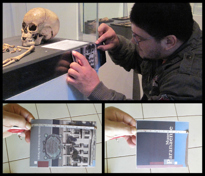
During this visit, the archaeologist Dr. Moacir Elias Santos and Dr. Liliane Cristina Coelho invited me to know the Paranaense Museum, where we took some fotos and I saw the real bones of a Brazilian aboriginal child.


Taking advantage of his know-how of 3D scanning by photos, Dr. Moacir Elias Santos took some photos of the aboriginal child with a good simple camera without flash, and without move the object.

Even with a low-illuminated scene, the photos had a good quality to be scanned.

Even though the scanning technique works well, it lacks an automated scaling system.  To solve this problem I used an folder that Paranaense Museum offer to the visitants. I made the measure folding it with the dimensions of the legend of the bones. After, I used it to get the dimensions with a measuring tape.

The scanning worked well on PPT-GUI. The points cloud had a good quality to be converted in a mesh.

Although the quality was good, the side of the skull that pointing to the wall wasn't reconstructed completely.

To solve this problem I mirrored the mesh on Blender.

And I erased the overlapping vertices.

The following step was put the tissue depth markers second Manheim et al. (2000). We choose the column of 8 years because the researchers said that the child was 7 or 9 years old.

With the tissue depth markers placed, It was possible trace the lateral shape of the face.

To make the facial muscles I used a pre-modeled muscles from other reconstruction and I deformed it to match with the skull.

The same process was used with the skin. It started with a pre-modeled mesh.

And it was deformed until match with the tissue depth and the muscles.


The following step consisted to sculpt the details on the face surface. The eyes was setted with asiatic characteristics second the observations of Dr. Paulo Miamoto, a doctoral student of forensic sciences.

Because we didn't have the information about the sex of the child I made a neutral reconstruction. In the final, the image illustrate a child with asiatic characteristics.


I hope you enjoyed.

A big hug!
BlogItalia - La directory italiana dei blog Creative Commons License
This work is licensed under a Creative Commons Attribution 4.0 International License.