Showing posts with label Archaeological documentation. Show all posts

Sunday, 2 October 2016

Torre dei Sicconi - Chapter 4 - Documentation

Working on archaeological documentation requires different types of equipment a techniques. Watch in this video some of them in action, while we are continuing to work on the picturesquely situated site of Torre dei Sicconi.

Enjoy!

Torre dei Sicconi - Chapter 4 - Documentation


Monday, 27 July 2015

Documentation of a bas-relief on a cliff : the workflow

This summer, between May and June, we worked for a joint mission, led by the University of Innsbruck (Institut für Alte Geschichte und Altorientalistik) and the Cultural Heritage, Handcrafts and Tourism Organization of Iran. The project was held in Firuzabad, in the Pars Province of Iran. We will write more details about this work in the next post. By now I just want to use some material we collected to illustrate the work-flow in data acquiring during an archaeological documentation of a bas-relief on a cliff.
The video below shows the overall process.


You can see the initial preparation phase (1), during which we placed the Ground Control Point (GCP) to perform normal 2D vertical photo-mapping and to rectify and georeference the 3D point-cloud. Than (2) we collected pictures with three different flights of our DIY drone, in order to use them with different open source SfM/MVSR software (PPT, openMVG and MicMac), to reach the best possible result: a couple of flights with parallel camera, to have a good superimposition of the whole bas-relief, and a higher acquisition to cover the upper details. In the meantime (3) another operator (+Rupert Gietl) was collecting pictures from the ground, to register also the lower perspective. Later (4), I prepared the total station and collected the GCP, thanks to some fixed points we placed the day befor (0) with our GPS. Finally +Rupert Gietl  took the last (very close) details photos, using a ladder.
The entire process lasted more or less four hours, but we needed some more time the day before to place the fixed GCP down in the valley (in international Geographic Coordinates System). A good part of the work involved just the logistics or the approach to the site, and has been slowed by the transportation of the necessary equipment (ladder, total station and drone) through a couple of passages where it was necessary to climb some rocks.
It is interesting to note that it would not have been possible to accomplish this mission with a commercial drone, due to the embargo rules (which are currently under revision), while with a DIY hexacopter it has been simple to disassemble the components which were not allowed (like the FPV system ore the GPS controlled flight).
I hope this post was useful, have a nice day!

Friday, 18 April 2014

How to take pictures for photomosaics in narrow conditions: A clever solution for a common archaeological fieldwork problem.


Everyone who works on archaeological excavations knows situations like this:


A narrow and deep trench or a wall near to the limit of the excavation area.

If subsequently we have to make a photomosaic of the profile or facade, it means:

  • either photographing from the top, hazarding the consequences like distorsion:

  • or splitting the photomosaik in numerous single tiles, and that means a lot of work!


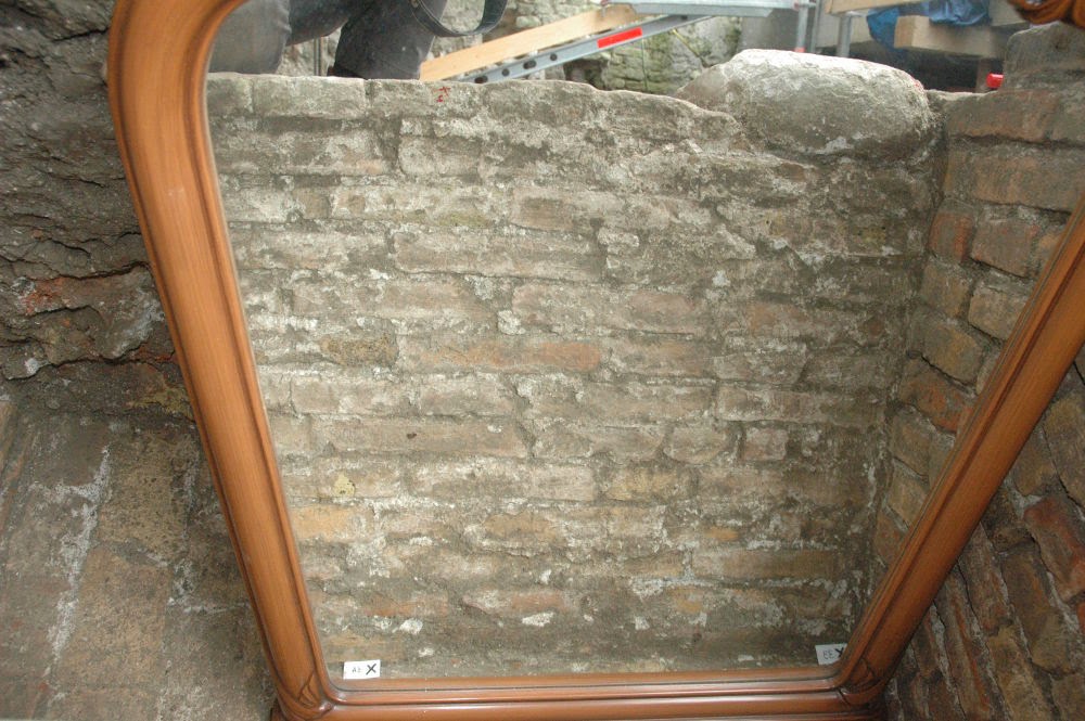
A very simple and clever solution for this problem can be the use of a mirror:

Putting it down in an inclined position on the ground and positioning yourself on the opposite side (watch the illustration beneath and heed me kneeing outside of the trench), it allows you to take a shot of the reflection of your facade in the mirror.

Of course the picture will show the object mirror-inverted, but don't worry:
The rectification software will fix it again...


Thanks a lot to Granma for borrowing us her wonderful kitsch bedroom-mirror!

Wednesday, 19 February 2014

Archaeological drawing symbols in QGIS

QGIS style tools for vector layers allow us to build custom symbols for archaeological drawings (plans and sections). In this post I will present some preliminary examples of customizable styles for graphically representing hachures and soil texture (clay, silt, sand and so on). For each, the .qml style files are downloadable from http://www.uselessarchaeology.com/ (section programming): you can put them in your QGIS project and/or add to QGIS style manager for testing and modifying.
Using vector styles makes the drawing more automatic and fast, because is no more necessary to draw manually each individual symbol. Furthermore, vector styles enable to change quickly the size of symbols when the scale changes: in such way there is no need to scale any single object.
The bulding of a new style is managed by QGIS style window: with button “Add symbol layer” is possible to make a new symbol joining 2 or more individual symbols. All symbols settings (dimension, angle, offset, etc.) can be changed in the same window.

Hachures
In plans, the edges of holes and ditches and the differences in level are represented with hachures. They are composed by an isosceles triangle and a line: the triangle marks the highest part of the feature, where the slope begins; the line represents the length and direction of the slope, with the end of the line showing the bottom of the slope. I created 3 different styles of hachure for point layers (hachure_pn), linear layers (hachure_ln) and polygon layers (hachure_pl).
For representing the differences in level, for example at the top of wall, I create a shapefile of points connected to an attribute table with two numeric columns named “angle” and “length”: the first column records rotation angle of hachures, the latter records the length of hachure's lines (where lines are not required, the column value will be always “0”). Then I draw points in the place where there are differences in altitude, I load hachure_pn style, I rotate each points with “Rotate Point Symbols tool” (in advanced digitizing toolbar) and I write the line length I desire in attribute table.
All settings are customizable: from “Marker – Advanced – Rotation field” you can set attribute columns for angle; from “Vector Field Marker” you can set attribute columns for angle and length; from “Simple marker” you can set triangle dimensions and offset: usually I give an offset that is half of triangle dimension for fitting the point to the line.
Hachure_pn style can be used also for linear or polygon features.


If I have to draw a scarp, I create a linear shapefile and I load hachure_ln style. It's possible to modify dimension of triangles, space between symbols, width of line, etc. changing parameters in QGIS style window.

For representing a ditch or a hole, I create 2 polygon shapefiles, one for top perimeter of the feature, one for the bottom limits. The top polygon is drawn by hachure_pl style and the bottom polygon is filled by white color: in the layer tree the bottom polygon must stay over the top polygon for covering the hachure's lines that exceed the slope. Like above, dimensions, space between symbols, offset and so on are editable in QGIS style window.


Soil texture
I post some examples of archaeological layers filled with symbols representing soil components: clay, silt, sand, silt-sand.

You have to pay attention to the settings of the these styles. Many symbols are set in map units and not in absolute measure (i.e. millimeters) to better fit the variation of scale during the display. For printing, all style settings must be changed according to the plot scale; for this purpose printing tests are recommended. Finally, I suggest to export in .svg format and modify the layout in Inkscape for adjusting the last details.
In future I hope to post other examples of archaeological styles. But if you have other ideas or you want to contribute with your personal QGIS archaeological styles, we could create a shared library of archaeological symbols for QGIS.


Denis Francisci


Sunday, 14 October 2012

Extreme SfM: precarious situations and workplace safety

This post is a further contribution regarding the main benefit of SfM: its versatility. 
Thanks to its speed during the phase of data acquisition, this technique allows us to intervene quickly in the case where the archaeological excavation exposes precarious situations, often related with collapsing structures.
The image below is good example: we were working in the vicinity of a church, checking the excavator. The left pictures shows the part of a wall which was exposed during this operation, while the right photo reports the same subject just twenty minutes later.

The wall befor and after the collapse
Luckily, seen the precaurious conditions of the structure, we decided to document it with SfM and IBM techniques, and this is the 3D restitution of the wall before the collapse.

The 3D model of the wall
However, the documentation of archaeological arthefacts before their destruction, is just one of the benefits of SfM (mainly related with the speed during data acquisition). In fact the versatility of this technique is strongly connected with the hardware we need to collect the data: a simple digital camera. This make it possible to work without the necessity of a direct contact with object to be documented (especially if we can support the excavation with a direct reflex total station, to record the Ground Control Points needed in the post-processing georeferencing operations). This way to operate lead to minimize the risk and increase the safety in the workplace. The images below regard an example of this situation: sometimes it happen to be called to evaluate the damnages of costruction sites, already underway without the archaeological control. In these cases it can happen to document precarious situation, but, using SfM techniques, there is no need to stand in risky places (like under a section with many gravel layers), because all the operations can be done from a safety distance.

The gravel section


The 3D puincloud (thin points)
The 3D pointcloud (thik points)
 I hope this post was useful, have a nice day!

Tuesday, 30 August 2011

Which GIS? OpenJUMP

We are often asked why there are so many GIS inside ArcheOS (GRASS, gvSIG, OpenJUMP, Quantum GIS, SAGA GIS, Udig). Today I start answering with OpenJUMP. This is my favorite software for an excavation GIS, due to its fantastic drawing tools (that make it similar to a CAD). So, from my point of view, OpenJUMP is the best GIS to draw vector layers from georeferenced photomosaics, like in the image you see below...


... but of course there are also many other tools, which sometime are usefull to handle excavation data (below you see the "warping" utility). Moreover the database integration in the program is pretty enought for this kind of small projects.


BlogItalia - La directory italiana dei blog Creative Commons License
This work is licensed under a Creative Commons Attribution 4.0 International License.